
| |


 |
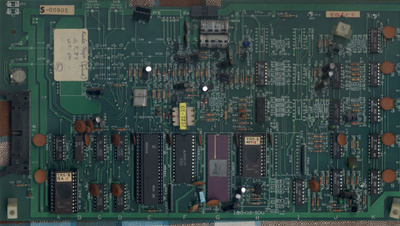
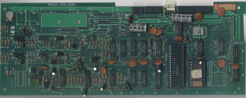
Click this picture to enlarge TRS2-03 SOU board. If you want to identify an unknown board and need a better picture, view this full sized TRS2-03 SOU board image (size is 346 KB) |
 |
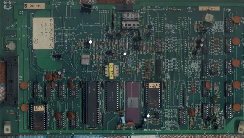
Click this picture to enlarge a TRS (I80)-02-SOU board with voice. If you want to identify an unknown board and need a better picture, view this full sized I80-02-SOU board image (size is 409 KB) |
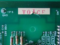 |
When i repaired the older TRS01 board variant in my cocktail
table i noticed a "VOICE" label on the sound board. I knew only voice-less
SOU boards of TRS02 before. |
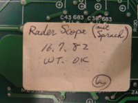 |
Also, on this board there was a tester's label which was dated July 16,
1982 and which says (in german) "with speech" |
| Sample file | Duration (seconds) | Size (KB) | Description | Note |
| cp01_voice_a.wav | 4.5 | 191 | "trouble, trouble..." | This is where the game starts |
| cp01_trouble.wav | 6 | 265 | (plus siren) trouble... | siren and voice (mixed) |
| cp01_voice_b.wav | 2.5 | 102 | "...checkpoint charlie (?)" | In wave, at the beginning (Part I) |
| cp01_voice_c.wav | 2.5 | 94 | "...checkpoint bravo" | In wave, after about 60 s (Part II) |
| cp01_voice_d.wav | 2.5 | 95 | "...checkpoint alpha" | In wave, after about 90 s (Part III) |
| cp01_voice_e.wav |
1 | 52 | "...Use caution!" | Almost at the end of a wave. (Part IV)(Thanks to c.h for this info!) |
| cp01_voice_f.wav | 2.5 | 94 | "complete attack mission" | End of wave |
| cp01_voice_g.wav | 94 | "engine trouble" | constantly when damage 100% |
| Sample file | Duration (about seconds) | Size (KB) | Description | Note |
| p01_start.wav | 9 | 394 | siren sound | from TRS02 (voiceless) version |
| p01_beep_and_background.wav | 4 | 102 | background sound | start beep and beginning wave |
| p01_attack.wav | 7 | 298 | attacking alien | from 1st wave |
| p01_shoot.wav | 3 | 145 | laser gun | from 1st wave |
| (to be continued) |
 |
This is the 7P SOU plug, named [P4 power in] on the TRS SOU board edge. see also in the power supply section. |
| Location | Signal Name | Signal description |
|---|---|---|
| P4 CPU - pin 1 | Noise | From separate noise generator, generates flickering of the stars. The "shot noise" is an electronic noise, generated by the flow of electrons through a highly-charged field (like a semiconductor junction). Here it is the inversely polarized base-collector junction of the NPN transistor (Tr 10). This transistor has its collector left open. The shot noise is not used for sound purposes but for a visual effect: it generates a random twinkling of the stars in Radar Scope (The Noise signal at P4 is labeled /STAREN on the CPU board and used to randomly switch the stars on and off) |
| P4 CPU - pin 2 | N.C. | Not connected |
| P4 CPU - pin 3 | ANS-I |
Output from sound board 8035 MCU, PB4 (Pin 35) going to the CPU
board. This signal acknowledges the execution of the startup sound
sequence. The line is held high (for about 8 seconds after the Start
button has been pressed) then pulses low three times after completion of
the startup siren sounds. ANS-I is renamed to SACK
on the CPU board (Its L active low signal of the 8035 is inverted two times on the CPU Board) |
| P4 CPU - pin 4 | SYSTA |
This comes from the CPU board and goes to the active low /INT line of the sound board MCU. During the initial startup sound (for about 8 seconds after the Start button has been pressed) this line is pulled low by the CPU |
| P4 CPU - pin 5 | GND | ground |
| 8035-pin11 | ALE | ALE is Adress Latch Enable, an output of the 8035. It occurs every cycle of the 8035 and you can use it as a clock output for connecting a signal analyzer. For example, when ALE goes low, an adress will be latched by the 74LS75 for IC19, which is the 2716 EPROM |
| P5 CPU - pin 5; 8035-pin4 | INIT |
Reset Input from CPU board, also resets the LS164 (serial in / parallel out) shift register on the sound board |
| P5 CPU - pin 14; IC17-pin8 | 2VF | goes to the clock inputs of the LS164 shift register and is used for the explosion sound |
| P5 CPU - pin1 | SYNTH0 to DB0 - pin 12 - of 8035 |
Synth Sound Data for MCU see table below |
| P5 CPU - pin2 | SYNTH1 to DB1 - pin 13 - of 8035 |
Synth Sound Data for MCU see table below |
| P5 CPU - pin3 | SYNTH2 to DB2 - pin 14 - of 8035 |
Synth Sound Data for MCU see table below |
| P5 CPU - pin4 | SYNTH3 to DB3 - pin 15 - of 8035 |
Synth Sound Data for MCU see table below |
| P5 CPU - pin6 | /SOUND0 | Sound trigger, going to IC9-pin1. Used for explosion sound; scratching noise |
| P5 CPU - pin7 | /SOUND1 | Sound trigger, going to IC9-pin3. Used for muting (?) of noise |
| P5 CPU - pin8 | /SOUND2 | Sound trigger, going to IC9-pin5. Used for noise |
| P5 CPU - pin9 | /SOUND3 | This goes to PB5 of the 8035. it is the indicator that the damage meter has been filled all the way. Essentially, it is how TRS1 boards with speech functionality knew when to play the "engine trouble" line. |
| P5 CPU - pin10 | /SOUND4 | This goes to the T1 input of the 8035, pin39; It starts the burning ships sound of the aliens when they go down. Used like an interrupt |
| P5 CPU - pin11 | /SOUND5 | This goes to the T0 input of the 8035, pin1; It starts the attack sound of the aliens when they swoop down. Used like an interrupt |
| P5 CPU - pin12 | /SOUND6 | Goes to IC9-pin9; Makes chirping high-pitched background space noise |
| P5 CPU - pin13 | /SOUND7 | Goes to IC9-pin11; This is the siren trigger. The siren is built with the 556 timer chip |
| P5 CPU - pin15 | GND | GROUND |
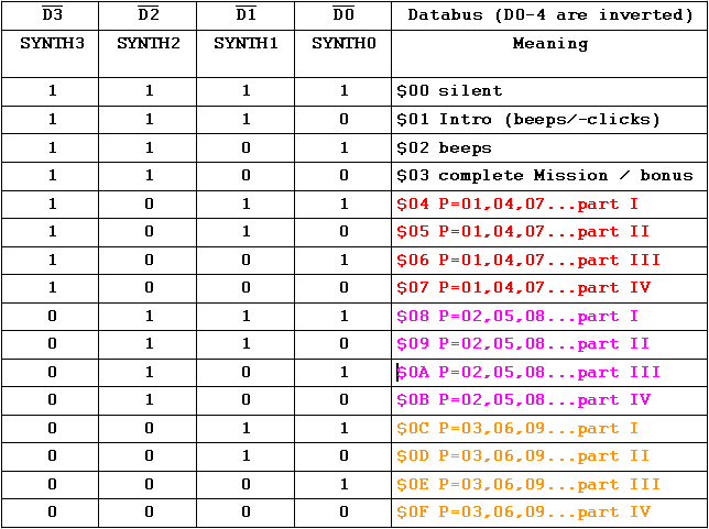
For example, when the CPU (Z80 on CPU board) outputs a $04 for the sound board, this lower nibble ($4 = 0100) will be inverted and appear as (1011) to SYNTH3-0. In the 4 columns to the left of the table you see the SYNTH data (1011) and in the rightmost column $04. P=01,04,07... means that this sound is heard in all phases (P) 01,04,07 and so on, and in the first part of the phase. Each P has four parts, increasing in difficulty. The overall style of the attack sound is the same, but the sound is sligthly different for each of the red 1,4,7..., magenta 2,5,8... and gold 3,6,9... colored P's.
Click on the wav sample links in the table below to hear how the settings for SYNTH0 to 3 apply. Each sample is about 4 seconds, about 200KBytes long.
| SYNTH3 | SYNTH2 | SYNTH1 | SYNTH0 | sample | comment |
|---|---|---|---|---|---|
| 0 | 0 | 0 | 0 | synth0000.wav | fast two tone background, part IV |
| 0 | 0 | 0 | 1 | synth0001.wav | four tone background, part III |
| 0 | 0 | 1 | 0 | synth0010.wav | fast two six background, part II |
| 0 | 0 | 1 | 1 | synth0011.wav | slow two six background, part I |
The Radar Scope siren sounding at the start of the game is not a sampled sound produced by the waveform generator described above. It is created with one half of the NE556 dual timer at position 3B. This is an IC which has two of the common 555 timers in one casing.
The 555 part responsible for the siren is wired as an astable, the timing resistors being R50 (47k) and R51 (27k). The timing capacitor is 33nF. The output at pin 9 of the NE556 is a 432 Hz square wave. This square wave is modulated with about 185 Hz from the oscillator at position 3C (4049, pin 4) which is fed to the "control voltage" input of the NE556 at pin 11. It makes the siren sound a bit more rough/uneven.
The result is then switched by a slow oscillator formed with the 4049 at position 3A, making the siren "attack" in ramps of about 1 Hz.
On a TRS2-04-SOU board, if you have the beep sounds but the siren is missing, follow the SOUND 7 sigal from where it comes into the board (see table below). It passes through an inverter (Pos. 2I) to the reset of the 556. So when SOUND 7 is low, the 556 Timer B will be enabled. Verify that this is working, check the 556 timer chip - output is pin number 9 - and the 4049 at position 3A. Check TR8 and TR9 as well as the electrolytic capacitors at C45 and C46.
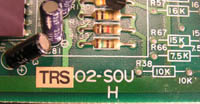 before removal of the label
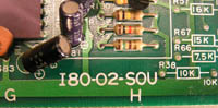 after
after


